8-bit CPU - Clock Module
This is the first post in a series that will detail my processes and learning experiences for building an 8-bit CPU from the chip level, and is not intended to be a re-writing of Ben Eater’s YouTube series. In this post I will detail the purpose of this first board, the basics of the components, how I went about constructing this first breadboard, and what I learned from the clock module.
Unsurprisingly, I began with the clock module for the CPU. This module is central to CPU as a whole and outputs a pulse or oscillation that synchronizes many of the discrete circuits within the CPU. Some examples of key pieces that use the clock to synchronize include the registers, RAM, and the various buses and links between discrete portions of the CPU.
Basic components of the breadboard clock are the 555 timer and logic chips that compose of ANDs, ORs, and NOTs. The 555 helps create pulses of varying length. I use the 555 timer in the astable configuration to create the oscillation which is used as a continuous clock for the whole CPU. It also can provide debouncing for the button and the switch. For this case a monostable 555 configuration is used for debouncing the button, allowing me to step a single clock pulse at a time consistently, while a bistable configured 555 is used to debounce the switch between debug and continuous clock modes. The logic chips are used to allow easy switching between the continuous clock and the manual pulse modes of the clock.
My personal goal for this project is to gain a practical and intuitive understanding of low level electronics, as well as having a chip level CPU I can easily extend and manipulate. To reinforce that goal I followed the same layout for the larger components that Ben Eater has done; chips, LEDs, and buttons/switches and forced myself to do the rest of the components and wiring myself. This allows me to follow the module to module layout, while still depending on my own thinking, reinforcing the concepts through recall and helping gain a deeper understanding of the overall schematic.
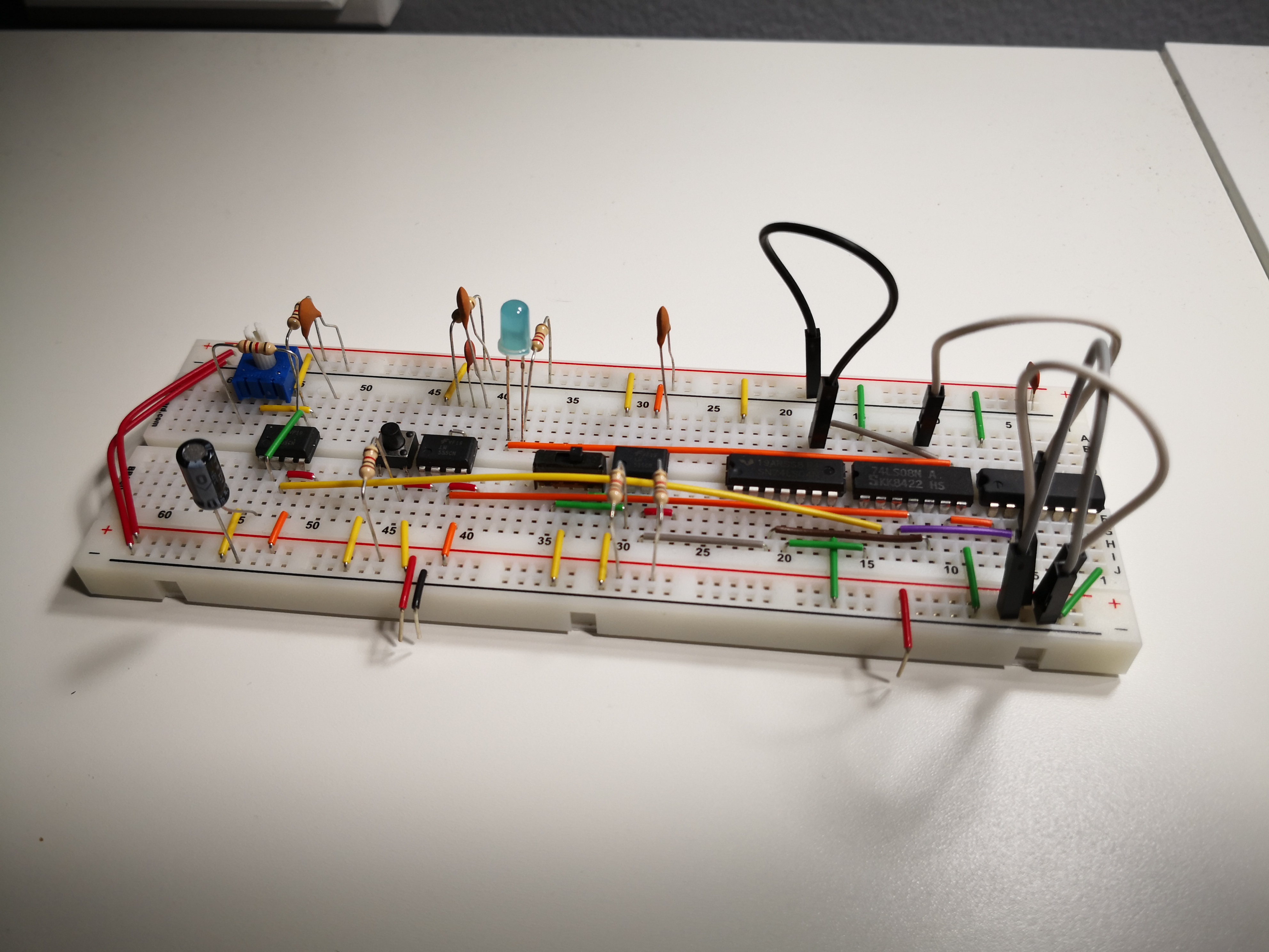
So I set out building the clock from the scaffolding provided, which ended up easier than expected. The monostable, bistable, and astable configurations for the 555 timer needed very few actual wires and components, that and using the pre-bent wire jumper kit made the clock module take only an hour or so to complete. The logic used to switch between the two modes was also quite simple to understand and setup on the breadboard. The construction of the clock module was simple and quick.
Overall, building out the clock module was simple. The hardest part was understanding how to configure the 555 timer for monostable, bistable, and astable operation as well as solidifying what each meant in my noggin. Learning how a 555 timer works internally and gaining confidence working with new and unfamiliar chips are my biggest takeaways from the clock module, consequently demystifying a lot of the relationships between chips in the coming modules.
I don’t see a step by step explanation of the clock module as necessary, given that in my experience. fumbling around is key to actually learning. However, if you believe it would help you let me know via email and I can see what I can do.
Part of 8-bit CPU project.
11 Dec 2019 - Written by Dominik Lameter

